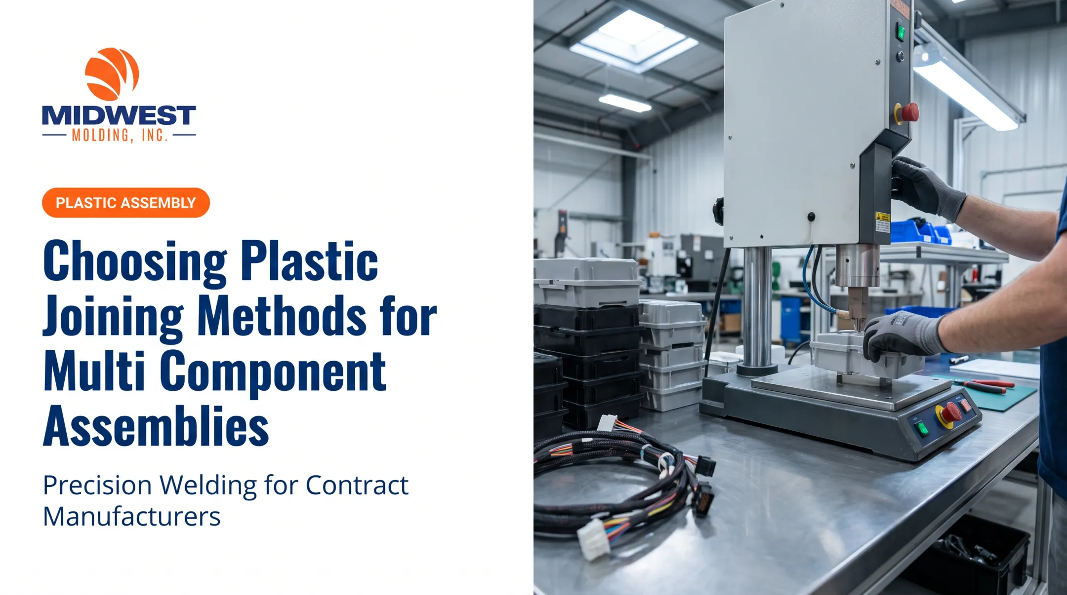

That's why joint design needs to happen before steel gets cut, not after a mold is already in production and welds are failing on the line. Energy director dimensions, wall thickness, locating features, and resin selection all get locked in at the mold design stage. Fixing them later means re-cutting tooling.
This article walks through a practical sequence: define what the finished assembly actually needs to do, pick a material and joint type that can deliver it, design the molded features for alignment and energy transfer, then validate everything through trials and inspection before committing to production tooling.
Key Takeaways
- Design joints for small initial contact, uniform perimeter contact, and lateral alignment together.
- Judge compatibility by resin grade, filler package, and moisture, not polymer family alone.
- Choose energy-director, step, tongue-and-groove, or shear joints for the strength, seal, and finish you need.
- Validate with pull tests for structural joints and leak tests for sealed assemblies.
What Ultrasonic Weld Joint Design Must Accomplish
Every reliable ultrasonic weld joint, regardless of part geometry, is solving the same three problems.
1. A small, controlled initial contact area. This focuses vibrational energy so melting starts predictably at one location rather than scattering across a flat interface. An energy director (a molded ridge at the joint line) is the most common way to achieve this.
2. Uniform contact around the entire weld path. A flat butt joint without an energy director touches first at its high points, so extending weld time just enlarges those local hot spots instead of melting the full perimeter. The result is flash in some areas and gaps in others.
3. Resistance to lateral movement during the weld cycle. Vibration happens at high frequency; if the parts can slide relative to one another, the joint won't form consistently, and cosmetic surfaces can show scuffing.
Joint design isn't just a welding problem, though. It's tied directly to what the finished part has to do in service:
- Structural load: Does the joint need to carry tensile, shear, or impact force?
- Sealing: Is this a low-pressure hermetic seal or a pressurized/liquid-retaining enclosure?
- Vibration resistance: Will the assembly see continuous mechanical vibration in use (automotive and appliance applications often do)?
- Permanent retention: Does the joint need to be destructive to separate, or is some rework expected?
- Cosmetic exposure: Will the weld line be visible, and does flash matter visually?
- Enclosed components: Are electronics, gaskets, or inserts captured inside the joint?
These requirements create real tradeoffs. A stronger joint often needs more wall section or interference, which adds material cost and mold complexity. A hermetic seal usually means managing more flash, since a tighter interference fit displaces more melted material.

A cosmetic exterior surface can restrict where the horn is allowed to contact the part, which in turn limits joint geometry options. None of this gets resolved by adjusting weld parameters after the mold is built. It has to be designed in from the start.
Choosing Materials for an Ultrasonic-Welded Assembly
Ultrasonic welding works by melting and re-solidifying thermoplastic. Thermosets cross-link permanently when cured and degrade under the localized heating ultrasonic welding generates, so they're not candidates for conventional horn welding.
Among thermoplastics, resin structure changes how the process behaves:
- Amorphous resins (ABS, polycarbonate, PETG) soften gradually through a glass-transition range, which gives a broader, more forgiving processing window.
- Semi-crystalline resins (nylon, polypropylene, acetal) have a sharper melt point and attenuate vibration more strongly as it travels from the horn to the joint. These typically need more amplitude and tighter geometry control.
Resin Grade Matters More Than Polymer Name
"ABS" is not a single material. It is a family of grades with different filler loadings, flame retardants, colorants, and mold-release packages, and each of those changes how the resin welds.
Glass or mineral fillers can help energy transmission in semi-crystalline resins, but high filler loading accelerates horn and fixture wear. Flame retardants frequently reduce finished joint strength. Recycled content can shift melt flow enough to change how an energy director behaves.
This is also why dissimilar-material welding can't be decided by a quick glance at a compatibility chart. Dukane's own Thermoplastic Compatibility Guide flags certain combinations (ABS to PEI, for example) as incompatible for ultrasonic welding, but the guide is explicit that actual results depend on the specific materials, part geometry, and testing involved. A compatibility chart is a starting filter, not a substitute for welding representative parts.

Moisture Is a Hidden Joint-Strength Killer
Nylon and some polycarbonate grades are hygroscopic: they absorb atmospheric moisture after molding.
If that moisture is present at the weld interface, it vaporizes under the heat of welding and foams the melt pool. The result is porosity, weak bonds, or a seal that fails under pressure testing it should have passed.
Practical controls:
- Weld hygroscopic parts soon after molding, or store them in sealed bags with desiccant.
- Don't confuse a pellet-drying spec (often ~0.2% moisture for molding) with the moisture condition of a finished, stored part. Those are different measurements for different purposes.
- Dry affected parts before welding if moisture exposure is suspected or confirmed.
Material-selection checklist before finalizing tooling:
- Specific resin grade and lot, not just polymer family
- Filler type, loading, and orientation near the weld line
- Expected service temperature and chemical exposure
- Required seal performance and weld strength
- Cosmetic requirements at the joint
- Representative trial parts welded and tested before production tooling is cut
That is why this kind of material verification belongs at the prototype stage, rather than discovering a compatibility problem after production tools exist.
Ultrasonic Weld Joint Geometries and When to Use Them
Four joint geometries cover most plastic assembly needs. The dimensions below are manufacturer starting points for verification against your specific resin and wall section, not fixed production tolerances.
| Joint type | Best for | Key tradeoff |
|---|---|---|
| Energy-director butt | Amorphous resins, simple alignment-tolerant parts | Simple and low-cost, but offers minimal self-location |
| Step | Cosmetic exteriors needing hidden flash | Needs extra wall thickness for the step feature |
| Tongue-and-groove | Low-pressure hermetic seals | Traps flash on both sides but adds molded complexity |
| Shear | Strong structural or hermetic joints, semi-crystalline resins | Requires rigid sidewall support; interference must be validated |
Energy Director and Butt Joints
The energy director is typically a triangular molded ridge with roughly a 90-degree apex, sized relative to wall thickness. It concentrates the horn's vibration into a narrow starting line so melt flow begins predictably rather than at random high points. This geometry suits amorphous resins well and keeps tooling simple, though a basic butt configuration offers little built-in alignment and can show some external flash.
Step Joints
A step joint offsets the mating surfaces so one part partially nests inside the other. This provides self-location, constrains lateral movement during the weld cycle, and can hide exterior flash behind the step, which is useful when the outside of the assembly is cosmetically visible.
The step needs enough wall thickness to stay rigid and enough clearance to absorb normal molded-part variation. Too tight a fit and normal dimensional drift causes assembly problems.
Tongue-and-Groove Joints
In this design, a molded tongue locates into a matching groove, with an energy director typically positioned on the tongue. The groove width needs to be slightly larger than the tongue (Dukane's guidance suggests a few thousandths of an inch of clearance) so the parts locate correctly without closing off the weld interface before welding begins.
This configuration is often recommended for low-pressure hermetic seals because it traps flash on both the inner and outer sides of the joint.
Shear Joints
A shear joint uses an interference fit where one wall overlaps another along a short, controlled lead-in. As the horn vibrates, the interference generates continuous melting along the full depth of the overlap, which can produce strong structural bonds and reliable hermetic seals. That makes it particularly useful for semi-crystalline resins that don't form a wide, gradual energy-director melt.
The tradeoff is rigid sidewall support: if the interference isn't validated against the actual molded part, the result can be excessive stress, cracking, or distortion instead of a clean weld.
Selection workflow: Start with material behavior (amorphous vs. semi-crystalline), then layer in load or sealing requirements, alignment needs, visible-surface constraints, horn access, part size, and whether the feature can actually be molded and inspected consistently. Joint selection that ignores any one of these tends to surface as a production problem later.

Designing Injection-Molded Parts for Reliable Welding
Joint geometry only works if the surrounding part supports it. A perfect energy director molded into a flexible, unsupported wall still won't weld consistently.
Near-Field vs. Far-Field Energy Transmission
Near-field welding means the horn contacts the part within roughly a quarter-inch of the joint itself. Far-field means the energy has to travel farther through the plastic to reach the interface.
Direct, near-field transmission is more efficient and more forgiving, especially with semi-crystalline resins that already attenuate vibration more than amorphous ones. Far-field welds often need more amplitude, time, and applied force to achieve the same result, so design for near-field contact wherever part geometry allows it.
Geometry That Supports Consistent Welding
- Uniform wall sections around the joint, avoiding abrupt thickness changes that create stress risers
- Adequate stiffness beneath the horn so the part doesn't flex or deflect instead of transmitting energy to the joint
- A weld interface that's as planar as practical, parallel to the horn contact face
- Generous radii at corners and stress-concentrating transitions
- No unsupported diaphragms or flexible appendages near the weld path that can absorb vibration instead of directing it to the interface
Let Molded Features Do the Aligning
Locating pins, sockets, ribs, steps, tongues, and grooves should establish part orientation, not the horn or the fixture trying to correct a poorly located part.
That approach needs a clear datum strategy and tolerance stack-up analysis so the joint stays within its intended collapse or interference range across normal molding variation, not just on a perfect first-article sample.
Flash Control and Cosmetic Management
Recessed weld paths, melt traps, interrupted energy directors, and hidden seams all help manage expelled material without leaving visible flash on exterior surfaces. The caution here: flash-control features that are too aggressive can also choke off complete fusion. A trap that's too tight restricts melt flow before the joint fully forms.

Horn, Nest, and Fixture Considerations
At the design stage, build in:
- A stable, flat horn contact surface
- Direct support beneath the weld path (not just somewhere near it)
- Clear tooling access for the horn and fixture
- No ribs, voids, inserts, or deep features that interrupt energy transmission on its way to the joint
This is where early collaboration between part design and manufacturing pays off. Midwest Molding's engineering support includes prototype and production tool build management, mold flow analysis, and ES testing alongside its sonic and vibration welding capabilities.
That combination catches alignment and energy-transmission issues during tool build, rather than after tools are cut and parts are already failing weld trials. Molding under IATF 16949 and ISO 9001 quality systems doesn't guarantee weld performance on its own, but having molding, assembly, and welding in one plant means those steps can be reviewed together rather than handed off separately.
Process Development, Inspection, and Common Failure Modes
A controlled development sequence keeps joint design decisions connected to real weld results instead of guesswork:
- Review CAD and resin data before any tooling commitment.
- Mold representative parts that reflect actual production wall sections and tolerances.
- Establish horn and nest alignment using production-representative fixturing.
- Run weld trials across a range of settings.
- Tune amplitude, force, and time (or energy and collapse distance, depending on the welder's control mode).
- Document a validated operating window, not just a single successful setting.

Common Failure Modes and Likely Causes
| Symptom | Likely cause |
|---|---|
| Excessive flash | Oversized energy director, excessive shear interference, or weld time run too long |
| Foamy or porous joint | Moisture in hygroscopic resin, often nylon or polycarbonate |
| Cracking near the joint | Sharp internal corners, excessive amplitude, or molding-induced stress |
| Weak bond or leak path | Molding variation causing incomplete melt, or misalignment during the weld cycle |
| Visible horn marks | Inadequate part stiffness beneath the horn contact surface |
Process settings often decide whether those failure modes show up in production. One Dukane study on polycarbonate parts welded with a rounded energy director compared rising-velocity and constant-velocity weld profiles. The rising-velocity profile produced an average failure load of 5,223 N, versus 2,432 N for constant velocity on the same part design and material.
That's a striking difference, but it's specific to that resin, part geometry, and equipment. It illustrates why process settings need validation against the actual application rather than borrowed from a different program.
Matching Inspection Methods to the Requirement
Don't run every test on every part. Match the method to what the assembly actually needs:
- Visual and dimensional inspection for cosmetic and fit requirements
- Pull or burst testing for structural joints
- Pressure or leak testing for sealed enclosures
- Sectioning to examine melt pattern and bond-line quality
- Weld-collapse monitoring and process-data review to confirm production parts stay within the validated window
Midwest Molding's use of quality software systems to segregate good parts from suspect parts supports exactly this kind of ongoing process monitoring once a validated weld window is established.
Conclusion: Design the Joint Before Cutting Steel
Reliable ultrasonic welding starts with design for manufacturing, not welder settings alone. Material compatibility, joint geometry, molded-part stiffness, alignment features, tooling access, and process validation all need to be considered together, before the mold exists, not after.
If you're developing a molded plastic assembly that will be ultrasonically or vibration welded, Midwest Molding's injection molding (under IATF 16949 and ISO 9001 quality systems), assembly, and welding capabilities support exactly this kind of integrated review. Reach out to discuss design, molding, assembly, and welding requirements before tooling decisions get locked in.
Frequently Asked Questions
What is the best joint design for ultrasonic welding?
No single geometry is best. It depends on material behavior, load and sealing needs, alignment, cosmetics, and tooling access. Energy-director joints suit simple amorphous-resin parts; step, tongue-and-groove, and shear joints address alignment, flash control, or sealing.
Can all plastic materials be ultrasonically welded?
Ultrasonic welding applies to compatible thermoplastics; thermosets can't be conventionally remelted. Even among thermoplastics, resin grade, additives, moisture content, and dissimilar-material compatibility all require actual testing, not just a polymer-family assumption.
What is an energy director in ultrasonic welding?
It's a molded ridge, often triangular, at the joint interface that concentrates vibrational energy into a small starting area for predictable melting. Its exact dimensions need confirmation against the specific resin, wall thickness, and tooling involved.
Are shear joints better than energy-director joints?
Neither is universally better. Shear joints often suit structural or hermetic seals and semi-crystalline resins with rigid sidewalls, while energy-director joints are typically simpler and effective for compatible amorphous thermoplastics.
How do you prevent flash in ultrasonic welding?
Accurate alignment, controlled melt volume, recessed or trapped weld paths, appropriate joint clearances, and stable tooling all reduce flash. Eliminating flash entirely can sometimes conflict with achieving complete fusion across the joint.
Can ultrasonic welding create a watertight seal?
Yes, when material selection, joint geometry, tooling support, and process parameters are all validated together. Pressure or leak testing should match the specific product requirement rather than assuming any hermetic-rated geometry guarantees seal performance on its own.