
Introduction
Cable overmolding is a material-selection decision that shapes how a cable performs for years in the field.
Get the resin wrong, and you'll see cracked boots, leaking connectors, or stiff cable exits that fail bend testing. Get it right, and the overmold delivers strain relief, sealing, insulation, and mechanical support that outlasts the application.
Material choice has become critical across automotive, electronics, appliance, consumer goods, and wire-harness applications. These cables face flexing, moisture, chemicals, heat, vibration, and abrasion daily. A molded strain relief joins the connector to the cable jacket and, in many designs, forms a seal at that same transition point, according to Molex's guidance on insert-molding tool design.
This guide defines cable overmolding, compares the major material families, walks through compatibility and design factors, and gives you a practical framework for choosing a material before tooling gets cut.
Key Takeaways
- Overmolding bonds a cable, connector, or insert with molded material for strain relief, sealing, and insulation.
- No single material fits every job; jacket, substrate, environment, and loads drive the choice.
- TPE, TPU, PVC, silicone, and rigid resins trade off flexibility, chemical resistance, temperature, adhesion, and cost.
- Validate material compatibility before finalizing production tooling, not after.
What Is Cable Overmolding and Why Do Materials Matter?
Cable overmolding places a prepared cable or cable assembly into a mold, then injects or forms a second material around a defined section of it. That second material becomes a permanent feature of the finished part.
Common functions include:
- Strain relief at the cable-to-connector transition
- Protection from moisture and contaminants
- Electrical insulation
- Abrasion resistance along high-wear zones
- Bend control that directs flex away from crimps or terminals
- Integration of mounting points, grips, or identification marks
Four Separate Decisions, Not One
It helps to separate four distinct materials in any overmolded cable assembly:
- Overmold material: the resin injected or formed around the cable
- Cable jacket or wire insulation: what's already on the cable
- Connector or insert substrate: the rigid plastic or metal the overmold must bond to
- Tooling material: aluminum or steel, which affects cost and cycle life, not the finished part's properties
Confusing these decisions is where projects go wrong. A resin that bonds beautifully to a PC/ABS connector housing may do nothing for the TPE jacket on the cable itself.
Material choice directly affects adhesion, compression, shrinkage, flexibility, surface feel, sealing performance, and dimensional stability. Pick the wrong grade and you risk poor bonding, cracking, excessive stiffness, flash, voids, leakage, or stress concentrated right at the terminal, exactly where you don't want it.
Avient's TPE overmolding guide identifies moisture trapped in either the overmold grade or the substrate as a documented cause of adhesion failure, alongside poor mold fit and excessive injection pressure as causes of flash. These are known failure modes, not rare edge cases, which is exactly why material selection deserves attention before tooling is cut, not after.
Cable Overmolding Materials: Types and Trade-offs
Five material families dominate cable overmolding. Grades within each family can behave very differently, so treat family names as a starting point, not a specification.
Thermoplastic Elastomers (TPEs)
TPEs are a common default for general-purpose strain relief, grips, seals, and cable exits. They process well in standard injection equipment, offer a wide range of tactile finishes (soft-touch to firm), and flex without cracking across moderate temperature ranges.
Watch for: chemical resistance and adhesion vary significantly by grade.
Avient's Versaflex selector guide lists OM 9-802CL at 40 Shore A bonding to PC, ABS, PC/ABS, and COPE substrates, while OM 6059-9 at 58 Shore A targets nylon substrates instead. Neither listing confirms bonding to your specific cable jacket, so that still needs verification.
Thermoplastic Polyurethane (TPU)
TPU earns consideration when abrasion resistance, toughness, flex life, and a durable handling surface matter most. BASF documents Elastollan grades, including 1185 A 10 FHF and the automotive anti-kink-bushing grade 1175 A 10, used to directly injection-mold a watertight joint between cable sheathing, a contact carrier, and a bushing.
That example maps directly to cable transitions. Still, verify for your selected grade:
- Stiffness at your operating temperature range
- Hydrolysis and chemical resistance (TPU can be sensitive to sustained moisture)
- Low-temperature flex performance
- Compatibility with the specific cable jacket in your design
PVC and Other General-Purpose Thermoplastics
PVC fits well when cost, process familiarity, standard colors, and moderate-duty protection are the priorities. Teknor Apex's APEX 4112 grade, rated for overmolding and injection molding, lists Shore C 70 hardness and a 75.0°C continuous-use temperature. That is useful hard data, but specific to that grade alone.
Review more closely when your application involves:
- Low-temperature flexing (PVC can stiffen significantly in the cold)
- Aggressive fuels, oils, or industrial chemicals
- Severe abrasion exposure
- Automotive under-hood environments
Silicone and Thermoset Materials
Silicone earns a spot on the shortlist for high flexibility across wide temperature ranges, strong environmental sealing, and specialized applications where thermoplastics struggle. Wacker's ELASTOSIL LR 3070/30, at 30 Shore A, lists adhesion to PA, PBT, and PET substrates with cable connectors cited as a representative hard-soft composite application.
The trade-offs are real, though. Liquid silicone's flow characteristics make flash control more demanding during molding. Cure conditions differ from thermoplastic processing entirely, and bonding is substrate-specific rather than universal across every connector material.
Rigid Engineering Resins and Hybrid Designs
Nylon, polycarbonate, PBT, and ABS often serve as the rigid substrate beneath a softer overmold, or as a standalone backshell providing structural support. These resins alone rarely deliver the bend relief a cable exit needs.
If you're pairing a rigid backshell with a flexible overmold, evaluate the combination for cable stress concentration at the interface, not just each material in isolation.

Material Comparison Criteria
Compare candidate materials against this checklist before shortlisting:
| Criterion | Why it matters |
|---|---|
| Flexibility and hardness | Determines bend radius and flex-cycle tolerance |
| Temperature range | Affects both service and storage conditions |
| Chemical and fluid exposure | Oils, fuels, cleaning agents, UV |
| Abrasion resistance | Relevant for cable runs that drag or rub |
| Flame and regulatory requirements | UL 94 and similar classifications |
| Electrical properties | Insulation resistance, dielectric strength |
| Adhesion strategy | Chemical bond vs. mechanical interlock |
| Processing and cost | Cycle time, tooling complexity, resin price |
A flexible outdoor sensor cable prioritizes UV and moisture resistance. An automotive harness prioritizes fluid and thermal-cycle resistance. An indoor appliance cable may prioritize cost and cosmetic finish over chemical resistance. Same overmolding process, three very different material priorities.
Design Factors That Affect Cable Overmolding Material Selection
Material selection can't happen in isolation. The cable jacket, connector substrate, insert geometry, and molding process all need to be on the table before a resin gets approved.
Cable Jacket and Substrate Compatibility
Overmold retention generally relies on one or more of these strategies:
- Chemical bonding: molecular adhesion between materials
- Mechanical interlocking: geometry that locks the overmold in place
- Compression: the overmold squeezing around the substrate
- Encapsulation: fully surrounding a feature or component
A material may bond well to one jacket and do nothing on another. Check the actual cable jacket, insulation, connector polymer, plating, adhesive, braid, and any existing heat-shrink or backshell components. Review supplier data sheets and run representative adhesion testing; don't rely on material family names alone.
Environmental and Mechanical Exposure
Document every condition the cable will face:
- Operating and storage temperature range
- Moisture exposure or full immersion
- Automotive fluids, cleaning agents, oils, or fuels
- UV exposure, salt, and dust
- Vibration, impact, repeated bending or pulling
Overmold geometry and hardness should move bending away from the terminal or crimp area without creating an abrupt stress riser at the transition point. Match material flexibility to your actual bend radius and flex-cycle requirements, not a generic "flexible" label.
Sealing, Wall Thickness, and Shrinkage
A material's shrinkage rate, flow behavior, and compression characteristics directly affect voids, flash, and sealing surface quality. Thin walls shrink differently than thick ones, and inconsistent wall thickness is a common source of warping and dimensional drift.
"Waterproof" is not a specification. Name the actual ingress target (IEC 60529's IP rating system, for example) and the corresponding test method whenever sealing performance matters. That IP rating applies to the finished enclosure or interface, not to a resin pellet on a data sheet.
Tooling and Manufacturability
Draft angles, parting lines, gate placement, vents, cavity design, cable positioning, and undercuts all influence which material actually works in production, not just which one looks good on paper.
Production volume changes the calculus too. According to Molex, multi-cavity tools cost more upfront but increase output and can lower per-unit cost at volume; single-cavity tools flip that trade-off for lower-volume runs. Aluminum tooling suits prototypes; hardened steel suits proven high-volume designs.
Validation Before Release
Build a validation plan that covers:
- Visual and dimensional inspection against drawing requirements
- Adhesion or retention testing at the overmold-to-substrate interface
- Pull testing per relevant acceptance criteria
- Bend or flex-cycle testing matched to real-world conditions
- Continuity, insulation resistance, or hipot testing where applicable
- Application-specific environmental exposure (thermal cycling, fluid soak, UV)

Define sample quantities, test duration, and failure criteria upfront. Set revalidation triggers for any change to resin grade, cable jacket, connector, geometry, or processing conditions. A "minor" substitution can undo validated performance.
How to Choose the Right Cable Overmolding Material
The right material is determined by your application's highest-risk requirement, not the cheapest resin or the most flexible option on the shelf.
A practical selection framework:
- Document existing materials: cable jacket, insulation, connector substrate, plating, adhesives
- Define the exposure profile: temperature extremes, fluids, moisture, UV, abrasion, flex cycles
- Set hard requirements: electrical properties, sealing targets, flame/regulatory standards
- Shortlist compatible grades: using supplier data sheets, not family names
- Validate with representative samples: under conditions that mimic actual use
Production quantity, tooling investment, color and cosmetic needs, supply continuity, and expected product life all factor into the final call. A grade that's perfect for a 500-unit prototype run might be the wrong choice at 500,000 units if lead times or regrind policies don't line up.
Involve molding, assembly, tooling, quality, and design teams early. A material that processes beautifully in isolation can still cause headaches if it doesn't integrate cleanly with the rest of the harness or assembly.
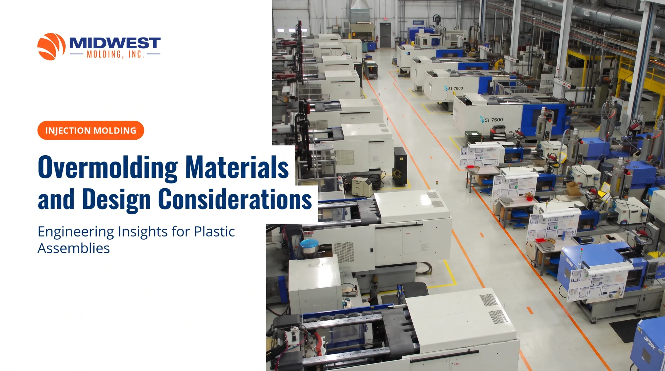
This is where a manufacturing partner with broad process capability earns its keep. Midwest Molding, based in Bartlett, Illinois, supports programs across injection molding, overmolding, insert and two-shot molding, and wire harness assembly, all under one roof, using 55 all-electric injection molding presses. That kind of integrated capability matters when your overmold decision touches molding, tooling, and assembly simultaneously.
What to Check Before Finalizing a Material
A few hard rules before you sign off on a resin:
- Don't approve on hardness, color, or feel alone. Confirm the exact grade, the current data sheet, lot controls, and compatibility with every material in the assembly.
- A successful prototype doesn't prove production readiness. Match the planned production cable jacket, connector, resin grade, tooling, and process conditions exactly.
- Watch for long-term risks: low-temperature cracking, fluid exposure over time, UV aging, hydrolysis, abrasion, creep, shrinkage, loss of adhesion, and stiffening after environmental exposure.
Before release, confirm your drawing specifies:
- Overmold length and cable support requirements
- Bend direction and flash limits
- Parting-line location and gate vestige
- Cosmetic surface requirements and dimensional tolerances
- Inspection points and change-control procedures
Midwest Molding's prototype and production tool build management includes mold flow analysis and ES testing as part of this verification step. New tooling is guaranteed for the life of the program.

Conclusion
Cable overmolding material selection shapes protection, strain relief, sealing, manufacturability, appearance, and long-term reliability, all at once. There's no shortcut around that.
TPE, TPU, PVC, silicone, and rigid engineering resins each solve different problems. Compatibility with the actual cable jacket and substrate matters just as much as the overmold material's standalone properties on a data sheet.
Define your operating environment and validation plan before tooling gets cut. Then bring in an experienced molding and assembly partner early enough that material selection, tooling design, and process capability can be worked out together, not discovered the hard way during a failed pull test.
Frequently Asked Questions
What is an overmolded cable?
An overmolded cable has a molded protective material formed around part of the cable or cable-connector transition. It typically provides strain relief, sealing, insulation, connector protection, and abrasion resistance in one integrated feature.
How does overmolding work?
A prepared cable or cable assembly is positioned in a mold, then surrounded with injected or formed material. That material cools (thermoplastics) or cures (thermosets like silicone) into the finished protective feature.
Is overmolding expensive?
Cost depends on material choice, part complexity, tooling design, production volume, cavity count, validation requirements, and assembly steps. Multi-cavity tools cost more upfront but can lower per-unit cost at higher volumes.
Is there a PDF version of this design guide available?
A PDF version is not available at this time. For technical resources or project-specific questions, contact Midwest Molding through the channels listed on this site.