
Design for manufacturability (DFM) for injection-molded parts means making material, wall-thickness, draft, structural, mold-layout, and assembly decisions together — not one at a time, late in the process. This article walks through each of those decisions in sequence.
One note before diving in: the numbers below are starting points, not guarantees. Every recommendation needs to be confirmed against your selected resin, part geometry, surface finish, tolerance requirements, and the specific mold design your molder proposes.
Key Takeaways
- Select resin and part architecture based on real operating conditions, not habit
- Keep wall thickness consistent, add draft and radii, and use ribs instead of solid mass
- Plan gates, parting lines, ejection, undercuts, and tolerances before cutting steel
- Validate with DFM review, flow analysis where warranted, and sample inspection
Start With Functional Requirements and Material Selection
Before any geometry gets drawn, define how the part will actually live in the world. That means documenting:
- Expected mechanical loads and fatigue cycles
- Temperature range, including peak exposure
- Chemical or moisture contact
- UV exposure and expected service life
- Electrical requirements, if applicable
- Appearance and cosmetic expectations
Resin choice drives nearly every downstream decision: wall thickness, draft angle, rib flexibility, shrinkage behavior, weld-line strength, and resistance to heat or chemicals all trace back to the material.
Amorphous, Semi-Crystalline, Reinforced, and Elastomeric: Different Rules Apply
Material class changes the design math. Covestro's research found unreinforced amorphous thermoplastics typically shrink less than 1%, while unreinforced semi-crystalline thermoplastics shrink more than 1%, with semi-crystalline resins generally more prone to warpage as a result of that higher shrinkage potential (Covestro, 2016).

Glass-fiber reinforcement complicates things further: fibers resist contraction along their orientation, producing directional shrinkage differences and strength that varies by flow direction. These are material-class tendencies, not promises for your specific grade. Confirm actual behavior with your resin supplier's data sheet.
Material selection also extends past mechanical strength:
- Regulatory or customer approvals (especially for automotive and electrical applications)
- Color and surface finish requirements
- Bonding or welding compatibility with other components
- Compatibility with metal inserts
- Resin availability and lead time
- Recycled-content requirements
- Total installed part cost, not just resin price per pound
For automotive, electrical, sensor, and control-device applications, confirm the exact resin grade with your molder early. Resin certifications, lot traceability, and performance documentation can all affect tooling decisions and the validation plan. Midwest Molding holds IATF 16949 certification for the manufacture of injection molded and insert molded products, which matters when a program requires documented process control and traceability from the start.
Quick material checklist: connect each functional requirement (load, heat, chemical exposure, appearance) to a specific resin grade, then confirm that grade against its supplier data sheet before freezing geometry.
Control Wall Thickness, Corners, and Transitions
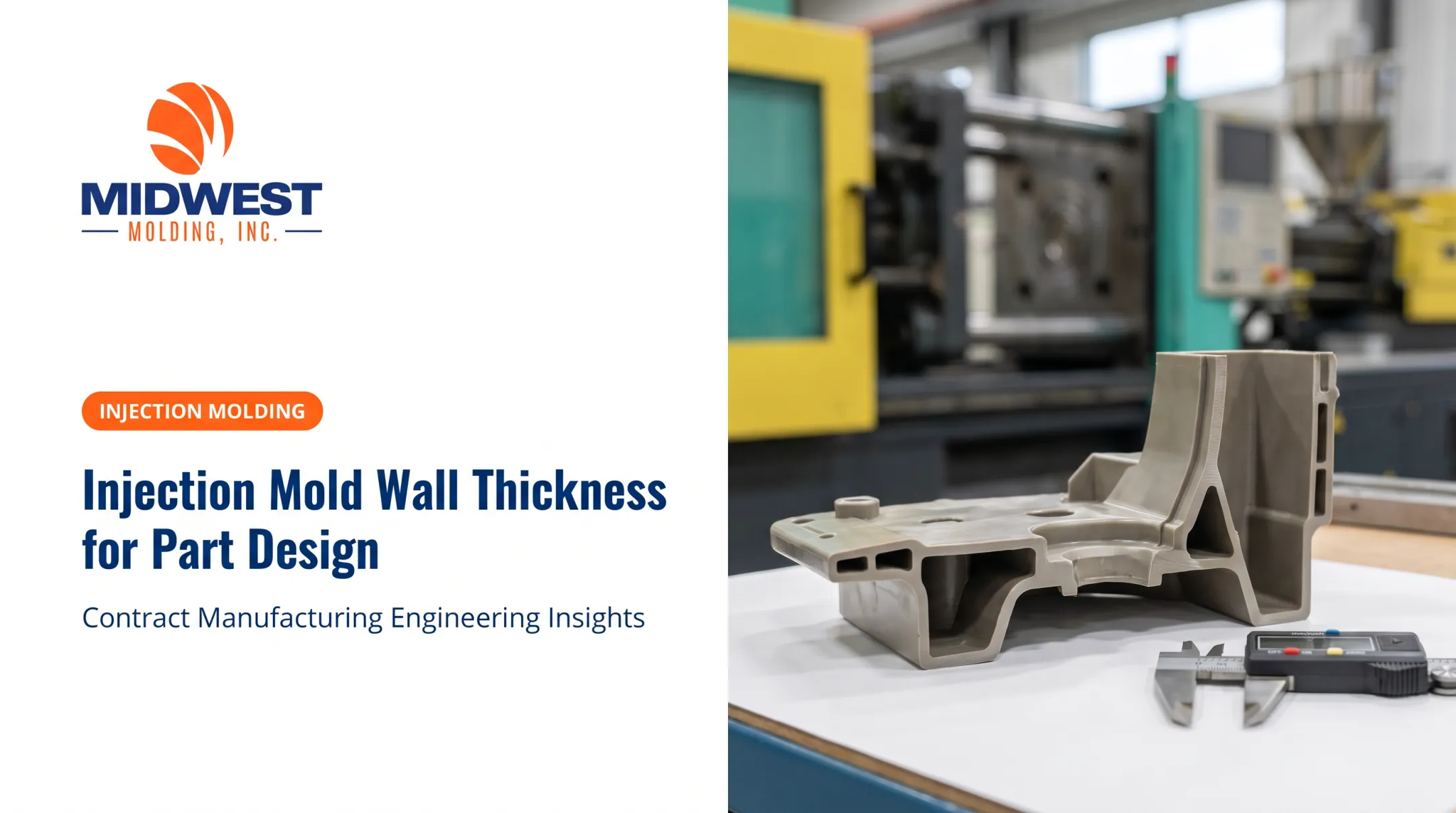
Uniform nominal wall thickness is the single biggest lever for predictable molding. Consistent walls fill more evenly, cool more evenly, and shrink more evenly.
Abrupt thickness changes, by contrast, are a direct path to sink marks, voids, short shots, weld lines, and warpage.
Published wall-thickness ranges vary by resin. Fictiv's design data offers these starting ranges:
| Resin | Recommended wall range |
|---|---|
| ABS | 0.045–0.140 in. |
| Polycarbonate (PC) | 0.040–0.150 in. |
| Polypropylene (PP) | 0.025–0.150 in. |
These are starting ranges for screening a design, not a guarantee for your specific part. Use them to size up a concept, then confirm with your molder.
Replacing Mass With Structure
Thick solid sections are rarely the right answer. Instead:
- Core out heavy sections to approach the nominal wall
- Use ribs or gussets to add stiffness without adding bulk
- Shell thick bosses rather than molding them solid
Managing Transitions and Corners
When wall thickness must change, blend gradually using chamfers or fillets rather than stepping abruptly. Sharp transitions concentrate stress and disrupt melt flow, which shows up later as warpage or cracking under load.
Corner radii matter just as much. A sharp internal corner concentrates stress and complicates tool polishing and EDM work.
A reasonable internal radius, paired with a proportionally larger outside radius, keeps material flow smooth and reduces tool-wear issues at the corner. Treat specific ratios as starting points that need review against your resin and geometry.
Common defect example: a thick boss molded next to a thin nominal wall often produces a visible sink mark directly opposite the boss. The fix is usually coring the boss and adding a fillet at its base rather than leaving it solid.
Add Draft, Ribs, Bosses, and Assembly Features Without Creating Defects
Draft
Draft is the taper on a vertical wall that lets the part release from the mold without dragging or scuffing. Draft requirements increase with wall depth and change based on resin behavior, texture, polish, and shrinkage characteristics.
A smooth, polished wall can often get away with less draft than a heavily textured one, since texture creates micro-undercuts that need extra clearance to release cleanly. Confirm the right angle for your specific surface finish rather than applying one number to every feature.
Ribs and Bosses
Ribs add stiffness without the weight and shrinkage risk of a solid thick wall. Rib thickness should stay at roughly 50–60% of the wall it intersects (Fictiv, 2023). Go thicker than that, or skip draft on the rib, and you risk sink marks on the opposite face, hard ejection, or warping as the part cools.

Bosses for screws, inserts, and dowels need the same discipline:
- Core the boss rather than molding it solid
- Add a fillet where the boss meets the base wall
- Apply draft to the boss OD and ID
- Space bosses far enough from walls and each other to avoid flow issues
- Verify height and wall thickness against the actual fastener being used
Assembly Features That Need to Survive Real Use
Snap fits, living hinges, threaded features, heat-staked inserts, and welded joints all carry repeated-use loads that a one-time assembly doesn't. Design decisions here depend heavily on expected cycle count and the resin's fatigue behavior.
This is where process capability matters as much as geometry. Midwest Molding supports insert molding, overmolding, two-shot molding, and sonic and vibration welding, all of which open up assembly strategies beyond snap fits alone. Not every design is automatically suited to every process, but knowing the options exist changes how you draw the part.
Design the Mold Interface: Gates, Parting Lines, Ejection, Undercuts, and Surface Finish
Mold opening direction and parting-line placement should be decided while the part is still in CAD, not after it reaches the tool shop. Parting-line location affects visible flash, dimensional control across the split, sealing surfaces, and whether the part ejects cleanly or hangs up.
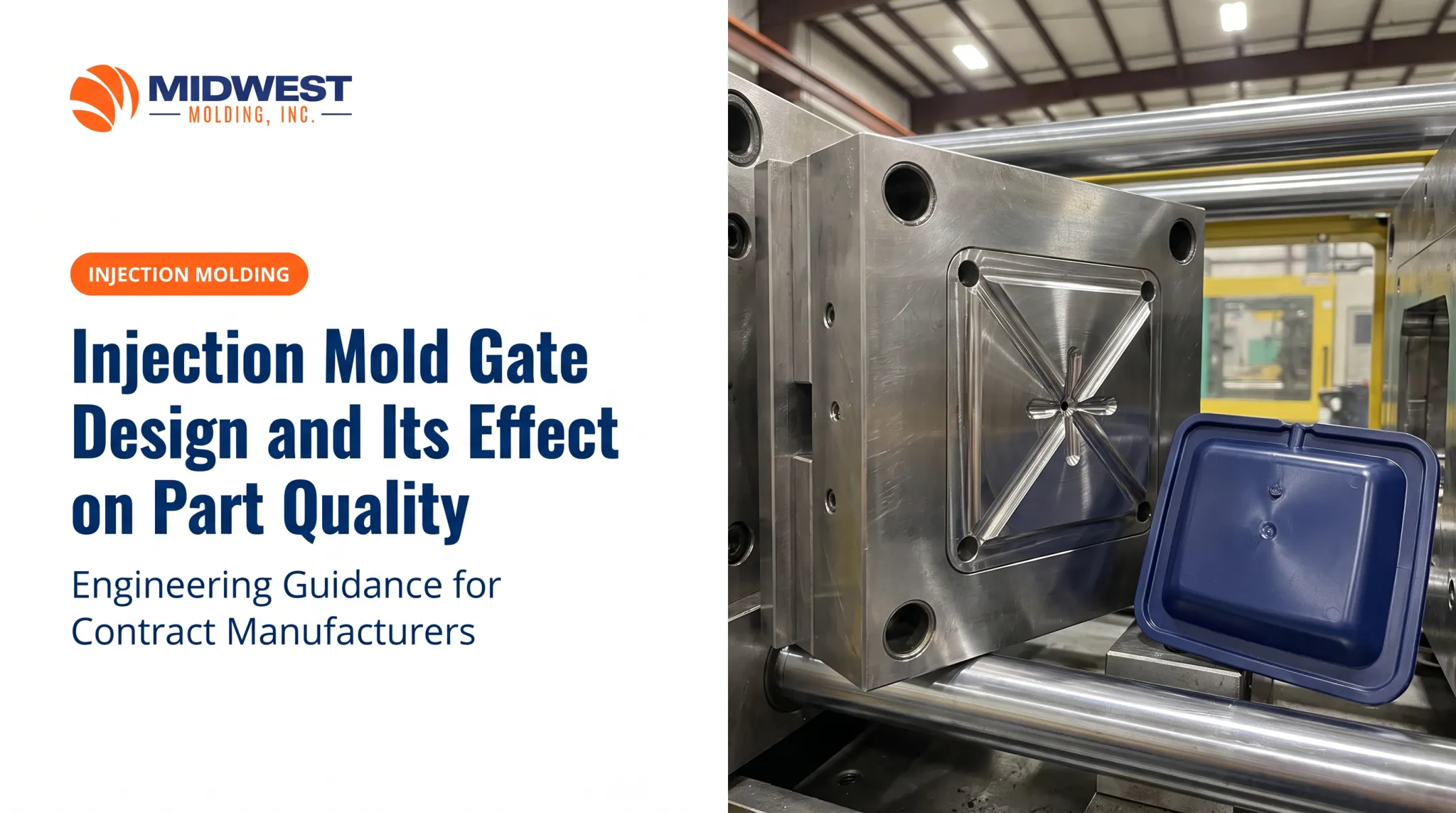
Gate type and location carry heavier consequences than many designers expect. A documented case from Plastics Technology found that two gates on a part produced a weak weld line, and switching to a single end gate resolved the functional failure entirely (Plastics Technology, 2014).

Gate position also drives:
- Filling balance and weld-line location
- Air entrapment, packing, and shrinkage
- Fiber orientation for reinforced resins
- Gate vestige and cosmetic acceptance
Ejection and Undercuts
Ejector pins need to act on areas rigid enough to handle the push without marking or deforming the part. Keep pins off cosmetic or sealing surfaces wherever the geometry allows.
Undercuts, internal threads, and side holes block straight ejection and typically require:
- Slides or lifters for side-pull features
- Collapsible cores for internal threads
- A redesigned part architecture, if tooling complexity outweighs the feature's value
Each of these options adds mold complexity, maintenance, and cost. Weigh that against the functional benefit of the feature.
Textures and Cosmetic Surfaces
Textured surfaces need more draft than polished ones because texture itself creates small release obstructions. Define cosmetic acceptance criteria, including grain direction and texture depth, before tool construction starts, not after first samples arrive.
A simple review sequence works well:
- Establish mold opening direction
- Locate the parting line
- Identify gates and vents
- Confirm ejection surfaces
- Evaluate remaining undercuts and side actions
Manage Shrinkage, Tolerances, and Validation Before Production
Shrinkage isn't a fixed number. It depends on several process and material variables:
- Resin family, grade, and reinforcement
- Flow direction and wall thickness
- Packing pressure, cooling rate, and mold temperature
- Gate design
Covestro's shrinkage research, noted earlier, shows meaningful differences between unreinforced amorphous and semi-crystalline resins. That data describes material classes, not a guaranteed figure for any single grade. Pull current data from your resin supplier and confirm it against your molder's process experience.
Tolerances: Nominal vs. Functional
Nominal dimensions describe the part as drawn. Functional tolerances describe what actually needs to hold for the part to work with its mating components. Tighter tolerances often mean more capable tooling, tighter process control, added inspection, or a different design approach entirely.
For assemblies involving mating plastic parts, inserts, fasteners, seals, or connectors, separate critical-to-function dimensions from noncritical ones early. A tolerance standard such as ISO 20457 can help frame acceptance conditions on the drawing, provided the edition is clearly specified.
Simulation and Sample Approval
Mold-flow or filling analysis can flag likely short shots, weld lines, air traps, warpage, and pressure issues before steel gets cut. Midwest Molding's engineering services include mold flow analysis as part of prototype and production tool build management, which helps catch these risks while changes are still inexpensive.

Once tools are built, inspect first samples for:
- Dimensions against the drawing
- Appearance and cosmetic acceptance
- Material identity
- Insert placement and retention
- Fit and function against mating parts
- Assembly performance under expected use
Pre-tooling checklist:
- 3D CAD model and 2D drawing
- Resin grade and color
- Texture spec and tolerances
- Gate and ejector expectations
- Insert specifications
- Inspection plan and production volume
Use a Cross-Functional DFM Review and Choose a Production Partner
No single discipline catches every manufacturability risk alone. Designers understand function, material suppliers understand resin behavior, mold designers understand tooling constraints, and the molder understands what actually happens on the production floor.
Getting all of them into the review before the design is frozen catches problems that are cheap to fix on paper and expensive to fix in steel.
A practical review workflow:
- Define functional requirements
- Select material
- Analyze geometry against DFM guidelines
- Confirm mold opening direction and features
- Simulate or prototype as needed
- Review samples against the spec
- Release the validated design
When requesting a manufacturability review, provide:
- CAD files and 2D drawings
- Resin requirements and estimated quantities
- Cosmetic surface callouts and critical dimensions
- Insert specifications and assembly steps
- Expected operating conditions
The more complete that package, the more useful the feedback.
While the review itself belongs to your design team, Midwest Molding can provide mold flow analysis and guidance on molding processes and parameters, drawing on injection molding, insert molding, overmolding, two-shot molding, assembly, and sonic and vibration welding at its Bartlett, Illinois facility.
The company's IATF 16949 certification for injection and insert molded products, along with a Delphi Pinnacle Award (2005), reflects the process discipline complex automotive and electronics programs require.
If you're developing a complex plastic component or an integrated assembly and want guidance on molding processes before tooling begins, contact Midwest Molding to discuss your project.
Frequently Asked Questions
What are the basic design guidelines for plastic parts?
Start with material selection based on real operating conditions, then maintain uniform wall thickness, add proper draft and radii, and use ribs and bosses instead of solid mass. Plan mold features and tolerances early, and run a DFM review before tooling.
What are the typical rules and guidelines for injection molding?
Key rules include establishing mold opening direction early, applying consistent draft, keeping wall thickness uniform, and planning gate and ejector locations before cutting steel. Undercut management, realistic shrinkage expectations, and sample validation round out the process.
What are the 7 different types of plastic?
Plastics can be classified by polymer family (amorphous, semi-crystalline, and so on) or by the resin identification codes 1 through 7 used on manufactured articles. ASTM is explicit that these codes identify resin type — they are not recycling guarantees.
How thick should injection molded plastic walls be?
Suitable thickness depends on the resin, flow length, part geometry, strength needs, and appearance requirements. Use a verified, resin-specific design guide as a starting point, then confirm with your molder rather than applying one universal number.
Why are draft angles important in plastic part design?
Draft lets a part release cleanly from the mold, reducing scuffing, drag marks, and ejection damage. The right angle varies with wall depth, resin, surface finish, and mold design, so it needs case-by-case confirmation rather than a single default value.